Yearly Archives: 2015


Fuselage 32 – Control System

Today was a relatively slow day. First I needed to interrupt my session for both a Lowes run, and a run out to my paint booth. Additionally, I was significantly slowed down by the weather, as its rainy with high humidity and my priming and painting was going slower than I’d like. I tried to get some other tasks done in the mean time, but it still killed my pace.

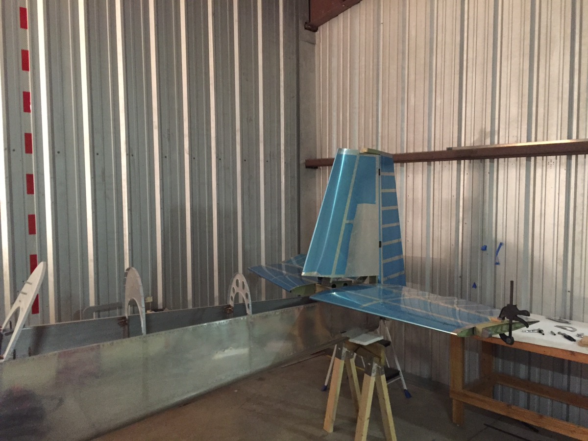
The first thing I did when I got to the hangar was check the elevator travel. I used my digital level and set the elevators to neutral. I then zeroed the level while resting on the elevator. I then put the elevator through its full travel to see if any adjustment would be required for the elevator stops. Yes, adjustment will be required to both the fore and aft stops. Luckily nothing is over, so I only need to file away some of the stops. I will return to this project in the near future and be sure to document it thoroughly.

Next, it was time to turn my attention to the control system. First up is the part for connecting the two control sticks to the elevator and aileron push rods. This needed to be final drilled in several locations. Quick work.

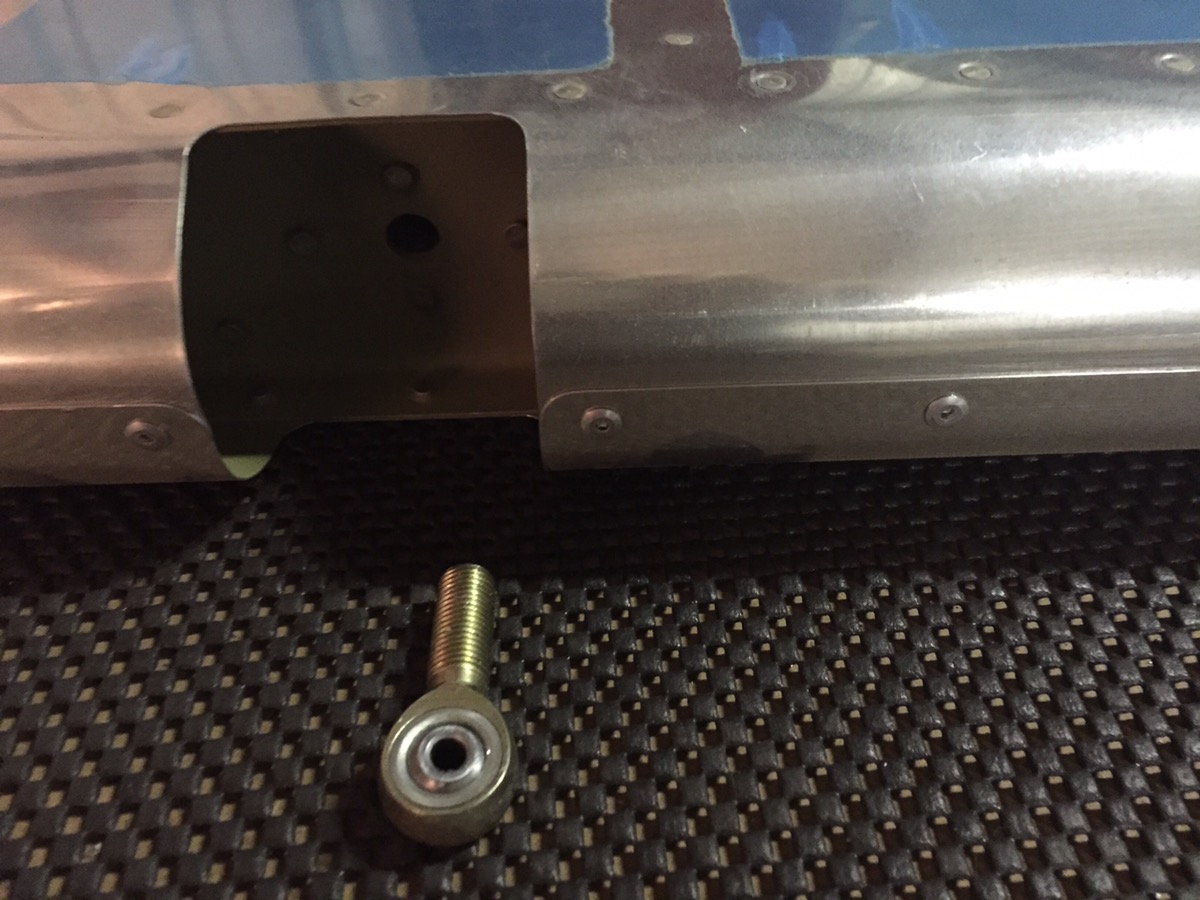
Next, the two bronze bushings had to be sanded down, and shaped to match the taper of the part.

Here you can see that there are two tapers to deal with. The part tapers forward to aft.  

It also tapers top to bottom. The method I used was simple. I clearly marked the top of the bushing and then slowly shaped and shorted the part as appropriate using the scotchbrite wheel. I took my time going back and forth to check on progress. When it got really close, I would mark the high and low points with the pen for minor adjustments. The result is spot on perfect. The reason you want to do this, is to prevent bending of the bushing under the tension of the bolt. This will prevent binding of the controls.

Here are photos of the bushing for the rear pilot’s stick.   

I did some additional work to the controls. I mounted the rear stick. This requires two measurements. One on the bottom portion of the stick, and one on the stick itself. Van’s tells you to drill them together, but I used a drill press and did them separately. First I did the bottom portion careful to keep 1/2″ and a perpendicular drill. Then I marked the stick itself with a line and made sure the line was centered in the bottom portion. I then taped the two together and drilled on side. Placing a bolt in that side, I match drilled the other side. The result is perfect. Perhaps a little more time that the Van’s method, but I don’t like match drilling circular items with the drill press, particularly when its difficult to see measurements and hold the parts together. This method prevented any error. Unfortunately, it looks like I didn’t take any pictures.

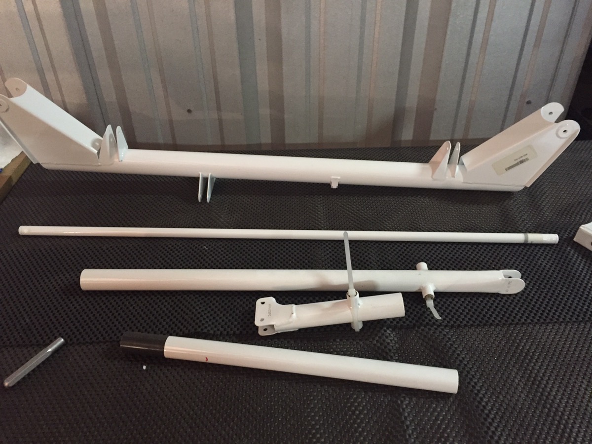
Some of the control columns are bright orange, and other parts are going to be smoke grey. The interior of my plane will have three primary colors. A very dark grey as the primary, and a lighter grey for certain accent parts like the control stick. Very small parts will be done in bright orange. The control rods, which will only barely & rarely be visible are orange. Orange is a good accent color, but if you overdo it, or haphazardly do it, the result will be tacky. Hopefully I get it right.


Session time: 6.0 hours 


Fuselage 31 – Elevator and rudder attach

Lots of tasks for today. First up I needed to finish the elevator installation. This required three tasks; trim / notch the rear spar to allow full travel of the elevator horns, trim the right horizontal stab skin to allow clearance of the counterweight arm, and finally match drill the bottom of the elevator horns for connection to the control rods.

I tackled the control horn, with the help of my buddy John, first. The process is simple.

First, measure the required edge distance per the drawings (3/8″ from the front and bottom of the AFT MOST horn). Then drill a pilot hole.

Use a drill press to drill a block of wood that fits neatly between the two horns, and use this as a guide to keep the drill perpendicular and even. Clamp the block in place and final drill, keeping a careful eye that the drill is level and perpendicular. 

img_9107.jpeg

Next up, notching the rear spar. I reinstalled the horizontal stab quickly to mark the required section for removal.

I forgot to take pictures of the end result before mounting the stabilizer on the fuselage. Here’s a photo after its mounted.

 Now its time to turn my attention to installing the static lines. I’m using the basic Van’s static kit. Yes, there are more expensive ones. Yes, some people don’t like the look of the stock pop-rivet static ports. I think they look fine. Reports indicate they work as good, if not better than pricier alternatives. Replacement will be simple! For the RV-8 the static ports are placed 4 inches below the longeron and 1 inch forward of the second bulkhead aft of the rear seat. (Both measured from the rivet centerline). Drill and install the pop rivets. I then used a hammer to pop the center portion out the back side. John held a block of wood to make the job clean and easy.   

img_9146.jpeg

Time to continue work on the control system installation. I riveted together the bell crank that is aft of the rear seat and connects the two elevator control rods.   

We also started installing the upper bulkheads. The aft upperdeck will soon be installed.

A few remaining items for the control rods. I still needed to prime the inside of both the elevator control rods, and rivet one.

My plane is going to be a mix of orange, silver, dark grey, and occasional black. I’m planning to make some internal parts bright orange. Here you can see all the push rods during painting. As these will not really be visible, I’m just using cheap rustoleum rattle can paint. As these parts were primed quite awhile ago, I scuffed the primer with scotchbrite and then wiped with acetone before applying the paint.

I reinstalled both stabilizers, and the control surfaces. Absolutely no binding. Everything seems to be precisely as it should be. I’m very happy so far. 

I made several holding clips for routing the static tube and primed those as well. 
Next time, it will be time to complete the controls!

Session time: 9.0 hours


Fuselage 30 – Mounting the elevators

I began today by riveting the newly fabricated F-884 attachment plate to the front spar of the vertical stabilizer. Before doing so, I shot the bottom of the spar with some primer to account for the cut that had been made a few blemishes in the AKZO.

Next, I reinstalled the stabilizers. It turns out I should have left the vertical stabilizer off.  

Time to begin attaching the elevators.

As soon as I attached the elevators, I realized I would need to properly install the rod end bearings, to ensure they were the appropriate distance prior to drilling the elevator horn, and trimming the horizontal stab skin for the counterweight arm.

Torquing the jam nut required an offset. You can find a great torque wrench adaptor calculator here.

I trimmed the skin of the horizontal stab for the counterweight arm on the left side. After doing so, I decided I’d do the other side when I remove the horizontal stabilizer. I still need to remove a portion of the flange on the rear spar to allow full travel of the elevator. But I can do that last, and I can trim the right side at the same time. 

Here are a few good photos of the trim result after cleaning it up. I’ll likely need more clearance when I glass the counterweight in, but I can trim more when the time comes and I know exactly how much clearance is required.   

My buddy Mike dropped off these bad boys. They are a godsend for temporary installation of the control surfaces. I had to shorten them slightly to make them work, but once I did, they made easy work of mounting the elevators. I’m not sure where he got them, but get yourself a set!

Next, I had to drill the upper pivot point of the elevator horns. To do this, you need to mount the elevators, and then lock them in position so they are true to the chord line. I used a clamp and a few blocks of wood on the counterweight arm to set the elevator in the appropriate position.

Next, you’ll need to make a bushing so the drill bit doesn’t hit the actual bushing. I used some spare aluminum tubing from the fuel tank vent lines. I had to use the soft scotch-brite wheel to reduce the diameter ever so slightly for a flawless fit.     

I initially drilled to a #30, and then slowly worked my way up to a 1/4 bit.

You can place a maximum of three (not including the steel washer) in between the horn and the hinge point. Unfortunately, at this point I have a small problem. There is not enough clearance between the head of the bolt (or nut) to attach a wrench. I can get a socket on the one side, but there isn’t enough room for the socket wrench, so I’ll have to do some thinking on this.   

I also took a selfie. Because. Instagram.

I made a quick reference guide pulling together a few torque tables from various locations. You can view it here: Torque

Session time: 6.0 hours