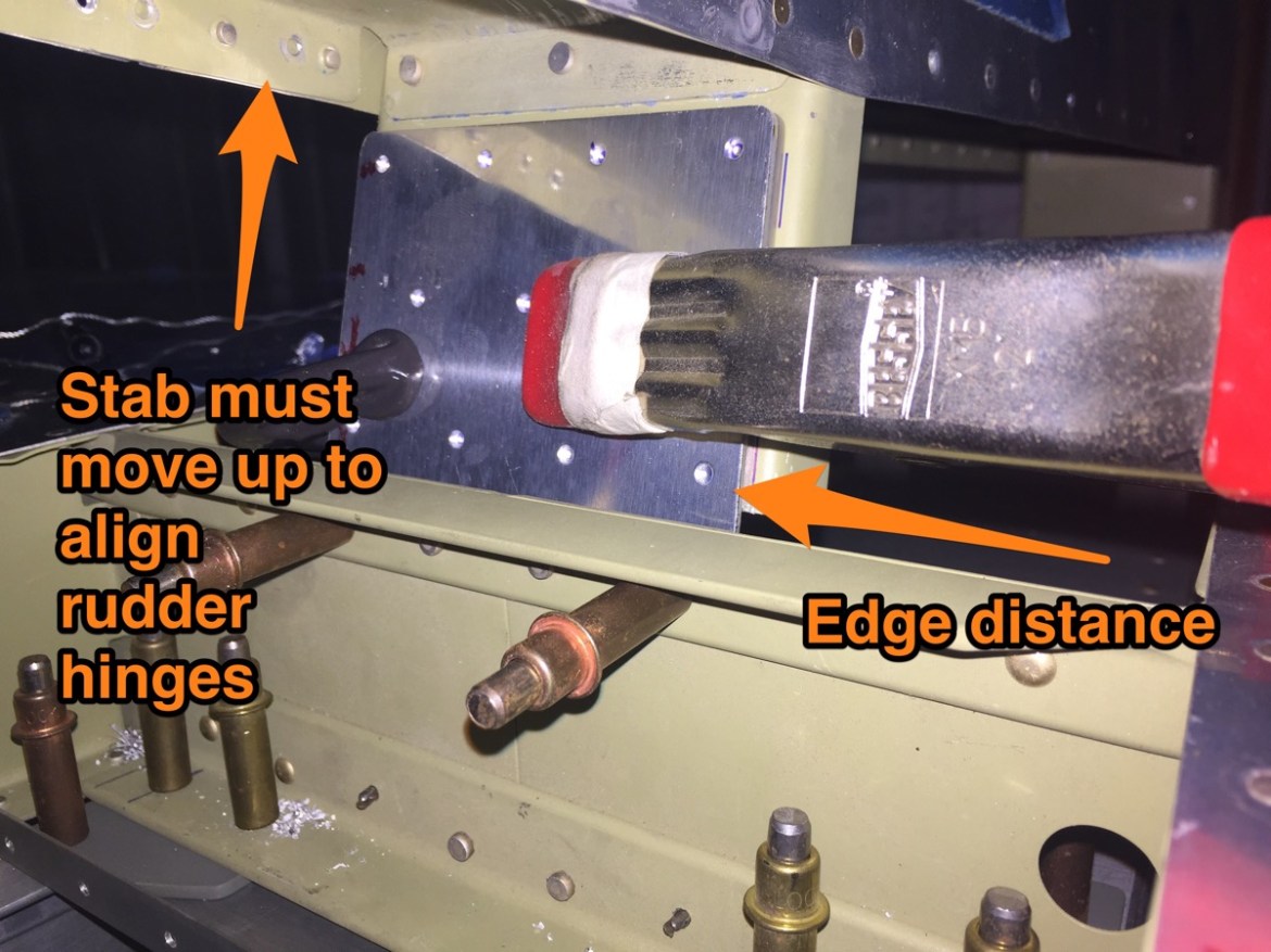
Yesterday I began the installation of the horizontal stab but I ran into an issue with the edge distance on the right longeron. After doing some research, I’ve found that Van’s considers the edge distances here to be “guidelines” and not hard and fast rules. The one solution I’ve seen people implement has been to turn the spacers into reinforcement brackets. The debate as to which edge distances are the most critical here is difficult to determine. Generally, I would default to the longeron being the most critical, but without a proper analysis of this particular joint, its difficult to say. This intersection shouldn’t see much load in sheer, as most load should be applied in tension. Regardless, I’ve decided to err on the side of caution and implement the reinforcement plate.
Here are the templates for the reinforcement plates. Note that the bottom one is not drawn correctly. I failed to connect the dots correctly. Don’t worry, I quickly noticed AFTER I made the cut. Needless to say I had to make a new one. Thankfully my buddy Jack was on hand with spare 1/8″ aluminum. 
Here are the end results. 
I removed the horizontal stabilizer and drilled out the one rivet forward of the horizontal stabilizer’s forward spar intersection, and the two aft. Match drilling these reinforcement plates was going to be a challenge. I began by clamping them firmly in place and match drilling the forward most rivet hole, and the inner most bolt hole.
With these then clecoed in place, I back drilled the remaining holes with Jack and Mike’s help.


Here you can see the reinforcement plates after drilling. I feel really good about this intersection now. The edge distances are not that far off, and with this reinforcement, I feel confident in the intersection. I’m further quite convinced that there are other areas that are more likely to fail before this intersection (I’m looking at you SB 14-01-31!)

Drilling the remaining bolt holes was not difficult. I back drilled them from underneath, and everything went perfectly. 

Here is a picture of the problematic right side. You can see that both the edge distances on the angle (orange lines) are within tolerance (and just barely.) However, the edge distance for the longeron is definitely on the short side. 
Here is the other side.

Next it was time to mount the vertical stabilizer. First off, you cleco and clamp everything in place. Then you measure from the top of the stab to a point on the elevator from each side. The point being to make sure the vertical stab is perpendicular to the vertical stab. 
I get 62 & 5/16″ on both sides. 

Camp the forward spar in place lightly. You’ll need to keep the spacer plate aligned. I did this by marking each hole position before installation.

The next portion is confusing. You’ll need to drill the three bolts that connect the tail spring. The problem is, the measurements on the diagram don’t make any sense. The reason they don’t make sense, is that they are flat out incorrect. Apparently Van’s has corrected these schematics since these were made. 
A little digging online, and quick consultation with the plans for Mike’s RV-7 resulted in the measurement shown below. 1 & 23/32″. A great explanation can be found at this kit log site: http://www.mykitlog.com/users/display_log.php?user=jpreou&project=45&category=2153&log=35967&row=212

Drilling these was fairly easy. Use lots of boelube as there is iron on both sides. 
Next its time to drill the two bolts at the top of the rear spar. Note I said TWO bolts, not THREE.


At this point it was time to call it quits for the night. I pulled the spacer/ reinforcements off. I wanted to prime them so they could be riveted in place next time.


