Yearly Archives: 2015


Fuselage 35 – Fwd elevator stop

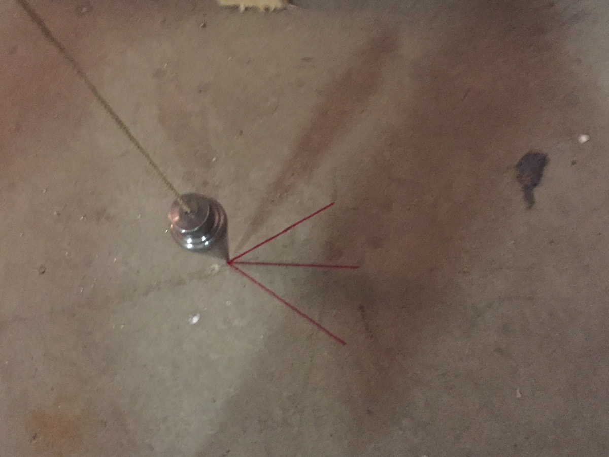
The first task for today was to remove the horizontal stab and elevator so that I could file down the forward elevator stop. The down travel of the elevator was 23 degrees, so I only had 2 degrees more for the down travel to be at its maximum deflection. Both elevator horns are supposed to touch the stops simultaneously, but in order to achieve this I would have to exceed the maximum elevator down travel. So removed as much as I could. This resulted in a 24.8 degree down angle, and about 1/16 of an inch of space between the right elevator horn and the stop. I will have to think on my solution for the down stop. Options are 1) leave it as is, 2) add a weld or rivet to the horn to account for the space, or 3) build out the right side of the stop in some way.

I also riveted on the aft stop.

After this, John and I began riveting the bulkheads to the fuselage. This took longer than you would expect as we needed to use several techniques. Some rivets could be squeezed, while others needed to be bucked using a variety of rivet sets and bucking bars.

We also made the wood inserts for laying inside the fuselage to do work.

I began the connection for the flap motor, but stopped, as I can quickly return to this after installing the floors for the final time.

I made an additional insert for the floors.   

Perhaps I should have done a few more things inside before clecoing on the turtledeck. For instance, running the rudder cables. I was able to get it done, but it was more work than normal.

As I got the rudder cable worked towards the front, I was confused trying to find the location for the cable going through the center section. After a little research, it turns out that they don’t drill this on the quickbuild. I assume a team makes this section for both the RV-8 and the RV-8A, and they leave it for later. The hole looking aft will be easy to drill. The hole looking forward (on the aft side) is going to be a royal pain in the ass to drill.  

I need to give some consideration as to how wiring will be routed to the empennage. I will have the aft strobe, and the elevator trim to wire up.

Session time: 7.0 hours


Fuselage 34 – Aft elevator stop

First, an update. After the last post, I was very concerned with a slight discrepancy between the alignment of the elevators. I posted to Rivetbangers and contacted Van’s support. The response from Van’s was:

Actually, that’s darn close to perfect alignment.  Nail it down before it gets away.

So, I’m still a little annoyed that its not perfect, but I guess I’ll have a beer and forget about it for now. If it still bothers me, I can fix it when its flying. I think it will likely be forgotten and a non-issue.

So tonight it was time to turn my attention to the rudder stops. The amount of travel that the elevators are supposed to have is 25 to 30 degrees up, and 20 to 25 degrees down. I used the digital level method to measure the travel. Before any modification, I only had 21.4 degrees up, so not even at the minimum. The down deflection is 23 degrees, so thats square in the middle of the range. Today I decided to work on the up travel, which means working on the aft stop.

Here you can see the aft elevator stop before modification. In addition to setting the correct amount of travel, you also should make sure that both elevator horns contact the rudder stop at full deflection. As most people’s horns are not symmetrically aligned, this means the stop will be different on each side.

I started by using a dremel, but it became quickly apparent that I would need more material moved to get the travel where I wanted it. This meant I needed to remove the rudder stop and use the bench grinder and scotch-brite wheel. 

Here is the end result. You can see the right horn further aft than the left. The final reflection is  27.5 degrees up. I may take off just a little more tomorrow to get closer to 30 degrees. Luckily, the front stop won’t require much adjustment. I will only take off a little bit for the left side of the stop to try to make both of the horns contact the stop at the same time. That should also get me pretty close to 25 degrees. 

Session time: 2.5 hours 


Fuselage 33 – Rudder & Elev Travel

Two projects for this evening. First, I wanted to check the travel of the rudder. The best way I could figure to do with was with a couple of plumb bobs and a protractor. I set a plumb bob at the hinge line and on the trailing edge. I then marked all points of the resulting triangle of movement on the floor.  
  

Using a straight edge, I connected the lines.
  

I used a protractor to measure the exact angles. 33 degrees in either direction. They need to be 30 – 35 degrees so this is right where it needs to be. I may file the stops slightly to get the full 35 degrees, and measure the distance to the elevators. Or I might not. We’ll see.
  

I removed the rudder and the vertical stabilizer. Next, I had two things to deal with on the elevator. First, alignment. There is a very slight mis-alignment.

With the elevator horn drilled, and bolted at both ends I clamped the right elevator at the counterweight. The result is a slightly high left counterweight arm. It only about 1/16th to 3/32″ max. It is most likely a slight misalignment in the elevator horn, but it could also be the counterweight arms, or the elevators themselves. Hard to say. I figured the trailing edge was more important, so I decided to examine that.

The best way I could figure to examine the trailing edge was to compare its level with one side clamped to the horizontal stab. I played around with multiple configurations. Using both a regular level, and a digital level.
  

Here’s the digital level on the horizontal stab. It reads 0.2 degrees high on the right.

On the elevator it reads 0.4 degrees high on the right. So thats a 0.2 degree difference. So the question then becomes, what to do about it? I checked the alignment of my buddies airplane. His isn’t perfect either, but better than mine. Although with the fiberglass done, its hard to tell. My instinct tells me to build on, but I’m trying to be as perfect as possible on the control surfaces and alignment. My options are either leave it as is, or repair, likely by welding and re-drilling the elevator horns. I could also possibly hide the slight disparity when I do the fiberglass work. I decided to email Van’s to see what they say.  

I also measured the up and down travel of the elevators. Both the fore and aft stops will need to be filed to match the offset horns, and to achieve full travel. Currently 23 degrees up (supposed to be 25 – 30) and 21.5 degrees down (supposed to be 20 – 25 degrees).