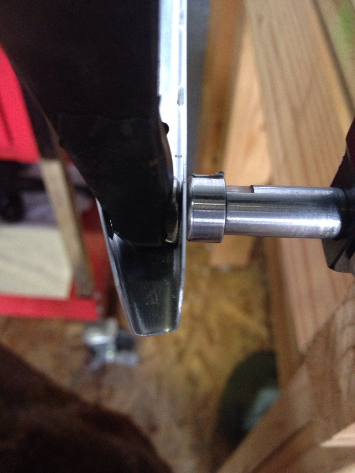
Today’s first action was to back rivet the aileron stiffeners to the right skin. I use simple scotch packing tape as my “rivet” tape.
I tape all the rivets for one side in place first. 
I use a large bag of lead shot to hold the skin firmly down on the back riveting plate. This is especially useful for the rivets that are very close to the trailing edge. As you pull the top side of the aileron skin up to access the shop head with the rivet gun the side you are trying to rivet will also want to lift off the back riveting plate… which is a recipe for a nasty mistake. 
Here you can see two photos of the end result. 

Next it was time to bend the trailing edge. I use a large bending brake made from wood with some simple door hinges courtesy of Mr. Bullock. Squire is always ready to help. With the ailerons, I had to use another 2×4 and the bag of lead shot to stop the skin sliding out of the brake. 
I am very happy with the results. A quick check with a rule showed that the radius is within limits and there is no bend or bulge. The skin is perfectly straight from the spar to the trailing edge. I also checked the trailing edge for any bow or distortion and there is none. 
I needed to lay everything out in order to be sure I was picturing it correctly in my head. 
The aileron hinge brackets need to be drilled for #12 bolts. I used a step bit. 
Its always important to keep the hangar well stocked with brews. They help you cope when you mess up!
I always tape the step bits when I use them to ensure I don’t go one step too far and enlarge the hole. 

I clecoed all the components together and set about match drilling.
The rivets on the bottom of the spar are drilled out to #30 in order to accommodate the CS4-4 rivet shown here. The aileron counterweight, otherwise known as a galvanized pipe, is also drilled out to #30. 

Use a long #30 drill bit to access the last attachment point for the counterweight. 

I haven’t gotten to use this yet, but my uncle gave me this, and I highly recommend it. This bad boy is perfect for the quick priming job or touch up. Mix your primer in the glass jar and boom you’re ready to spray. The propellant lasts enough for about a jar and a half. No cleanup, setup or air compressor required! I wish I had discovered this awhile ago.  Finally, the components will need to be dimpled. A word of caution here. Van’s doesn’t mention anything in the instructions about dimpling the leading edge to counterweight. Be careful. Normal dimpling methods will distort the skin due to curvature of the skin at this point. The method most builders use, and I will detail further when I do it is to use the countersunk counterweight pipe as the female die.


