Fuselage


Fuselage 16 (4.0 hrs)

First up, installing the filter on the compressor. Now, you’re supposed to install filters downline, at least 50′ from the compressor for maximum effectiveness. Right next to the compressor, most moisture will pass straight through. Regardless, I don’t have the room, time, or desire to plumb my portable compressor, so this will have to do. 

A little riveting action holds it all in place!  

With this complete, its time to start the installation of the rudder pedals. To make things easier I removed the bulkheads from the baggage compartment. While I’m at it, I’ll put new primer on those puppies.

I am installing the ground adjustable rudder pedals. The first step is to mark a centerline on the two angles that will hold the rudder pedal axels to the floor.   

Then you need to work on the friction bushings for the rudder pedal axels. I hate working with this plastic. Be careful how you orient the cuts and holes. Van’s, in true form, has provided the absolute bare minimum amount of material.   

After cutting the pieces out, I drilled the largest center hole first. This allowed me to mount the friction bushing and then match drill the final two smaller holes.

I used the first completed bushing as a template for the second.   

Here are the finished products.

Next, I put the rudder pedals together to check certain measurements.   

First you need to check that the outside edge of the angles is 15 1/4″ apart. As you can see, I’m spot on. 

This needs to be 1″ from the floor. Bang on again.  

Now this is where things get interesting. Earlier, I had to drill out, and replace a few AN470 rivets with flush pop rivets. However, the holes for my angles are immediately overtop of these rivets. I double and triple checked the measurements. 

Here’s a close up. You can see the center of the pop rivet almost directly underneath. There is no way this is going to be drilled for another rivet. I suspect it will have to be left empty.
  

The same is true at the other end.

I’ve labeled all the appropriate measurements, per the drawings, so I’m not sure why its so far off.   


As you can see here, the rivet I replace should not be directly underneath the angle. I don’t see any solution except to forego putting a rivet in this location. 

At the forward side, you are supposed to file a slight relief. This will not work in my circumstances. I’d need to file half the angle away! I’m going to sleep on this and then possibly contact Van’s support to see if I’m overlooking something.   

Update August 17, 2015: Solution to the above problem can be found here: http://papalimabravo.com/construction/fuselage/fuselage-18

The last project for the day was to start on the rear rudder pedals. I primed the insides and then drilled for the threaded ends. I cleaned the primer off later with acetone. 


Fuselage 15 (3.5)

First off, I have a hangar laptop! We had an old, very old, Sony laptop laying around the basement. The laptop is probably vintage 2006, and was anemically running Windows 7. It was so slow it was almost unusable. It probably was last used in 2010. I decided to re-purpose it. I wiped Windows off the system and replaced it with Lubuntu a light version of the Ubuntu Linux OS. Now the laptop runs just fine, and I will keep it at the hangar in an attempt to keep better track of things via this blog. Further, I can use it for research and probably most importantly; Pandora.

Secondly, Bryan from Showplanes contacted me. He has received my final payment, and hopes to have the kit shipped in the next two weeks. He also spent some time with me discussing canopy options. I have been looking at Todd’s canopies, but I think I will stay with the standard Van’s canopy.

I also spoke with Van’s about the parts I was missing in a previous post. The side consoles are missing, and it turns out they are supposed to be installed as part of the quick build fuselage! As a result they are sending me the replacements free of charge, and I included a couple of odds and ends to include a plans CD so that I can have the electronic plans on hand. We also discussed engine mounts, and he corroborated my research that the dynafocal 1 is the most common. As a result, I will soon submit my finishing kit order. I have multiple parts I will be deleting from the order. Those parts not needed due to the fastback conversion kit, and I will also leave off the rubber engine mounts, the tires, tubes and tailwheel which I will replace with other parts.

With all of those updates out of the way I turned my attention back to the fuselage. I’m essentially ready to either prime or mount the empennage, so I’m going through the instructions and picking out parts that I can prepare for priming in advance of when they are needed. I began this in the last post with some parts for the elevator horn. Today, I turned my attention to control rods. Van’s will tell you to cut a piece of paper to the circumference of the pushrod and then fold it in half three times in order to create the 8 equidistant rivet holes.  

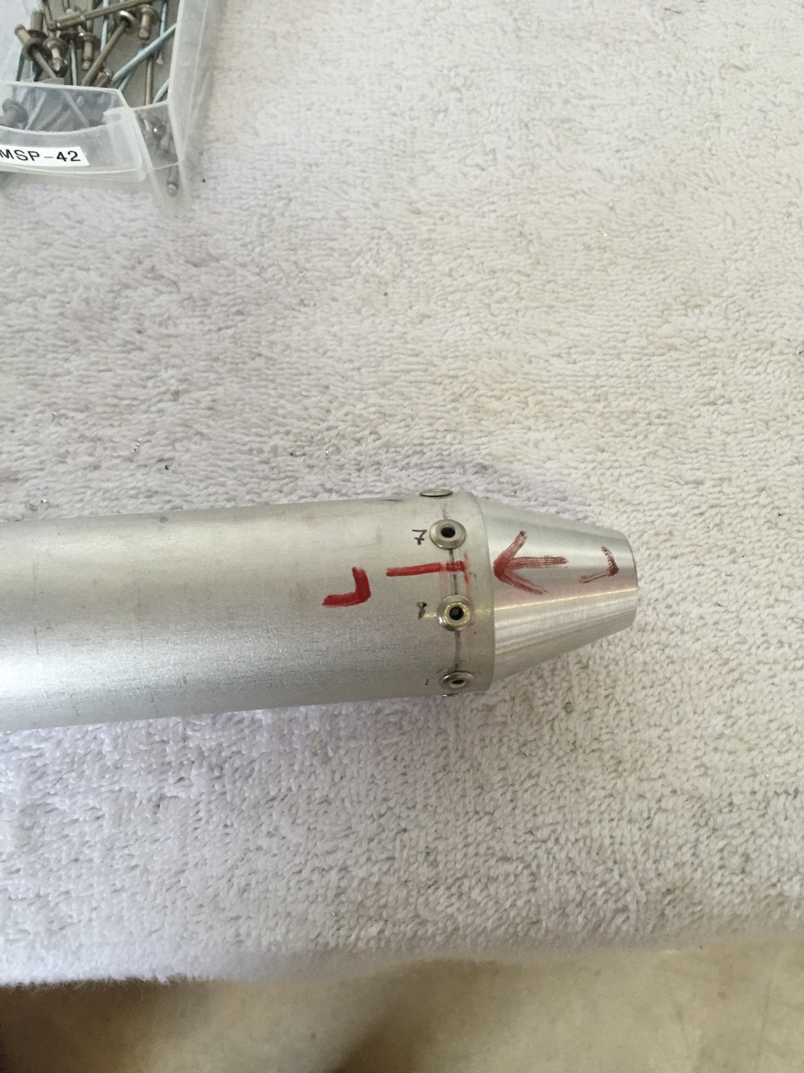
I do essentially the same thing, less the folding. I measured out the circumference, divided by 8 and then measured that out.  
  

The pushrod will need to be primed both inside and out, but Van’s tells you to clean out the inside and rivet the rod ends before doing so because the rod ends can be darn near impossible to insert after priming. Here’s the result.  

I repeated the above process for the other pushrod. This one will need to be primed prior to final rivet for rather obvious reasons. I finished off the evening session by drilling the second control rod. 


Fuselage 14 (2.0)

Tonight I began working ahead in the instructions in order to have as many parts for priming as possible. Here is the pile of parts I have so far.  

I also needed to complete the gear installation. The alignment was done previously and all the main holes have been drilled, however, both of the wear plates required two outboard holes to be match drilled.  

Here is where the inner wear plate still needed to be drilled.   

The results of that drilling from inside the fuselage.   

The outboard wear plate required a little more access in the bottom skins before it could be drilled.   

I enlarged those holes enough to drill a proper straight hole through. The predrilled holes in the skins are not properly aligned. And then I still had a little more material to move from where the bottom skins rub the gear legs themselves.  

Here is an after photo.  

Next I skipped ahead to a few parts for the elevator control horn and bearing. These will need to be primed.     

Lastly, I cut the main control rod to length.