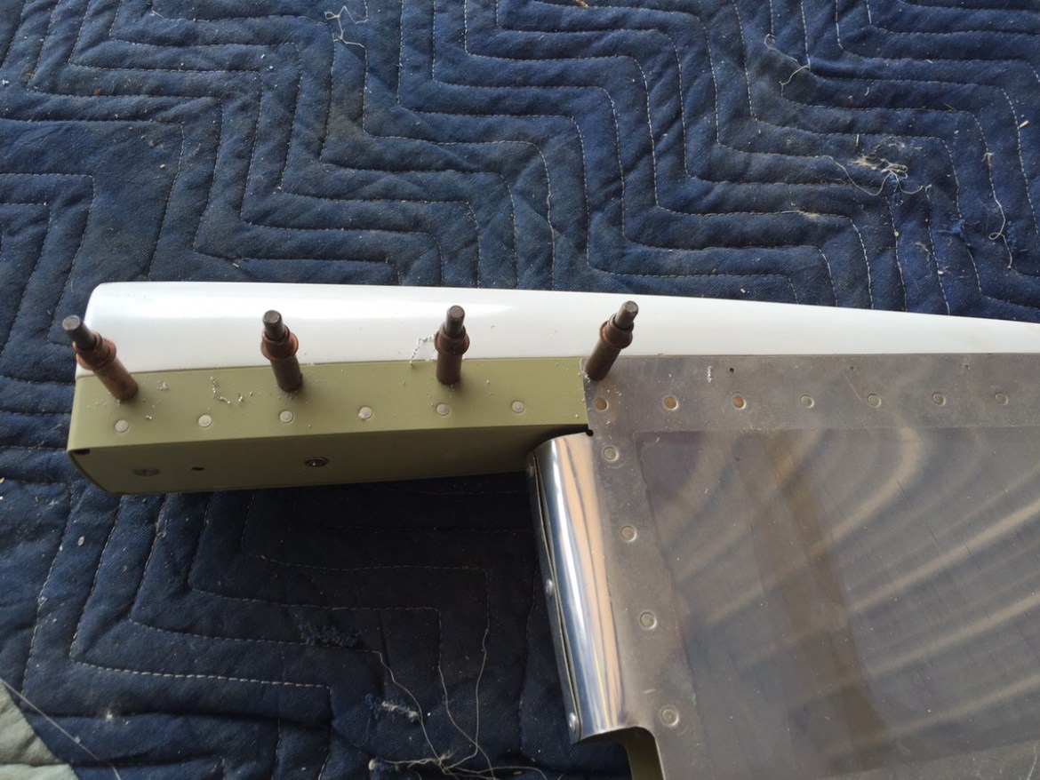
So today was all about the instrument panel and instrument panel cover (or glare shield). The Show Planes Fastback includes a rather substantial modification to the stock Van’s RV in this area. The forward fuselage skin is cut substantially back, and in its place is a custom fiberglass piece. This piece is held in place by nut plates and screws. This allows the canopy frame to sit flush with the aircraft when closed, and results in a spectacularly well finished product.
But first, the instrument panel itself. While the showplanes kit doesn’t explicitly call for this, I noticed the modification in some of their photos and decided to replicate it. The modification removes a portion of the frame (shown below) to allow more room for instruments. Additionally, the new instrument panel covers the entirety of the panel frame so that you have one flush clean panel surface.
The first step is to remove the portion of the frame to match the cockpit layout. 
Sidenote: I also completed the remainder of the riveting for the forward skin, less the rivets behind the gear tower. If you are doing a showplanes modification, be very mindful of the rivet lengths. The side rails are different and you’ll need longer rivets.

Still on the side-note, I used the scotchbrite wheel in the angle grinder to make doubly sure my double flush rivets are perfectly smooth on the skin reinforcement strip that will connect to the fiberglass panel cover.

Back to the panel. After the panel was cut, I gave it a quick prime. This will likely need to be done again, as there is much more mucking around to be had with this puppy. But this will get primer in all the parts prior to riveting.

Here you can see the modified frame in the cockpit. Notice how the lines going down the side match the showplanes ribs.

I was able to purchase some 0.063 2024T3 for fabricating the new instrument panel. Here you can see I’ve used the frame to make a rough outline for the cut. **NOTE** As I learn later, if you are making the same modification as I am, bend the bottom of the panel in a brake BEFORE making the cut! It will be far easier to fit and finish this way!.

After the first cut, I made some more measurements and made more rough cuts.

At this point I was able to place the instrument panel in the cockpit and on the frame. Again, if you haven’t bent the bottom, there is still time! I used a series of clamps to hold the panel in place and slowly adjust it. I then used a large marker to mark areas that were too large. The scotchbrite wheel made quick work of adjustments.

Now, here’s the rub. I’ve got this nicely fitted instrument panel, and I still have to bend the bottom. As the top is perfectly fitted, the bottom bend will need to be darn close to perfect or the panel will be in trouble.

To make final adjustments and ensure the panel was in the same place for every adjustment I drilled the screw holes for the top of the panel.

My buddy Mike took the instrument panel to see if he could bend it with the brake at work, but unfortunately that brake was only 24″ and couldn’t accommodate the full width of the panel.
On to the instrument panel cover or glare shield. Here is the fiberglass cover stock from Show Planes. The first step is to properly position the cover in order to mark a line 3/4 back from the edge of the skin. The skin should be 5/8″ from the concave portion of the fiberglass. To do this I centered the piece and then measured the distance from the cockpit rails on each side. Several small adjustments later, I was able to draw the line.


For the first cut, I went oversized so that I could come back and make a second cut after drilling all the holes. You’ll also need to cut the bottom of the sides in order to fit the part under the skin. Drilling the part, and maintaining the proper alignment was a challenge. The part wasn’t perfectly true, and I had to use a little elbow grease and a heat gun to get things lined up the way I wanted. It was a very slow and incremental process. Particularly on the right side.

After all the holes were drilled, I began work on the side fillets. This requires measuring the height of the fillets from the cockpit side-rails and then trimming appropriately. Measure twice! And err on the side of caution when you make your cut.


**EDIT 6/30/2016: The following is incorrect. You cannot taper the instrument cover. It must be trimmed flush for two reasons. First, the canopy skirt will not close (there is a bulkhead 1/4 inch behind the instrument panel), and second, its completely unnecessary as the canopy skirt will provide the practicality I describe below.*** The instructions call for cutting the cover essentially flush with the instrument panel. I don’t like this. While it does result in a clean and sporty look, I don’t find that to be terribly practical. I wanted some overhang for shade and lighting purposes. However, if you leave the entire overhang, you’ll have a odd intersection with the fillets on the side. I decided to do a taper from top to bottom. The top center 6 inches are 1.5 inches and then taper slowly and in a smooth curve down to flush at the bottom of the panel.

Here is a good photo showing the taper. The orange line parks the instrument panel frame. The next two photos also give a good side view of the fillet after much fine tuning. **See EDIT above**

Here is one with the instrument panel as well.

The fillet required a lot of work to get a nice transition on the side. Here you can see how I have perfect alignment with the cover (A). The gap show in (B) will be fiberglassed in. 
Here is a picture of the alignment. This isn’t actually the final picture. I did a little more work and completely removed the gap to the left of the fillet.

Here you can see the right (un-modified) fillet next to the left (modified) fillet.

Same comparison. Original on the left. Modification on the right. For some odd reason, in my head these were two separate pieces. Mike pointed out that it should be one piece. I stepped back and realized that was patently obvious and was a little miffed that I had missed something so readily apparent. All the more reason that getting these parts aligned perfectly will be fruitful. I can’t want to get it finished up!


