Monthly Archives: November 2015


Fuselage 25 – Prep for empennage attachment

My hangar mate’s plane is out for its annual inspection, so I have a few weeks where I have extra room. I decided this was the perfect opportunity to get started on the empennage attachment.

I knew I’d need a second set of hands to remove the fuselage from the rotisserie and get everything situated. Luckily my buddy Mike was willing to help. The first step was to rearrange the hangar as best I could and prepare space for removing the fuselage from the rotisserie.

After we removed the fuselage from the rotisserie, Mike was kind enough to keep my mobile platform in the back of his hangar. While he put that away, I built a quick and dirty fuselage stand from some basic saw horses.

Here you can see the fuselage in its new location. I’ve offset the tail to allow for the empennage to be attached.   

Fancy? Nope. Effective? Yes.

We put the tail feathers in place just to see it. Its a good feeling. This actually looks like a plane! I can’t wait until the wings go on!  

In the next session I will begin work on the actual attachment of the empennage.   


Fastback 12 – Vert Stab Modification

The Showplanes Fastback is slightly higher than stock at the intersection of the turtle deck and the vertical stabilizer. As a result, the front of the vertical stabilizer must be trimmed to allow sufficient clearance. 175 degrees to be exact. I bought a protractor on my way to the shop today, and presto here’s the result. Before this photo was even taken, I removed all the appropriate rivets. 

As you can see, this doesn’t allow the existing rivet holes to be placed nicely in the new layout. The new line is close to the second hole, and essentially bisects the next two. I gave careful consideration to how I should approach this problem. Online I found a few pictures, but nothing with enough detail. I found one builder who build a new rib. I briefly considered doing this as well. Getting the existing rib to fit, turns out to be a challenge.
  

Next, nothing to do but start the cut!

I really didn’t want to have any chance to harm the front spar so I protected it with some scrap aluminum I had laying around.   

Here’s the part that has only one photo, but took a ton of time!! Fitting that rib into position. I wound up fluting the nose and redoing some of the flange bends to narrow the nose of the rib down. I also redid the rear flange bend to pull the entire rib aft. This is a better solution (in my mind) than creating a new rib from scratch (which for me, is something I’ve never done).   

Here’s a good picture of where the previous rivet holes are after the cut. Not optimal. If I keep the same holes in the rib, there will likely be some of these that are very close together, especially those closes to the spar. I measured, and the aft most rivet (not in the spar) would almost touch one another. That won’t do!

The best solution I came up with was to create three new rivet locations aft. You can see them marked here. I was able to keep approximately the same spacing, and ensure that there was ample edge distance for every new hole.   

As for the old holes, I flattened them, and made sure they were as smooth as possible. They each have a firm new rivet on either side of them, which according to the acceptable methods of aircraft repair is the appropriate method.

I filled in the holes with a little JB Weld. Not for strength, but to build the primer / pain on to later.

Here’s a good picture of the end result. I’ve tried to diagram where the original holes are in the rib, and where the new ones are. The original holes in the skin are fairly obvious.   

Apparently I missed the note to leave these spots empty for the fairing. I did the same thing on the elevator. Man, what a newb I was then!

Next, I pulled the horizontal stab down, and removed the elevators. (They were just placed there temporarily for storage). I’m considering taking care of Service Bulletin 14-01-31 before installing the empennage. This is a bear of a project, so I’m not convinced yet. It isn’t required unless cracks form in the spar. Until such time the only requirement is yearly inspection. However, this project will not become easier after installation.   

I do not have the required relief notches. Upon review you can see them in the drawings, but there are no reference to them in the instructions.

Again with the fairings!  

Session time: 7 hours


Fuselage 24 – Rails, rudder pedals & more

I’ve done a lot of traveling in November, and I’ve not updated this blog accordingly when I have had time to get to the shop. This post comprises several shop sessions (3 or 4 I think).

First I finished up the cockpit rails. This included rivets that would be under the forward upper fuselage skin.

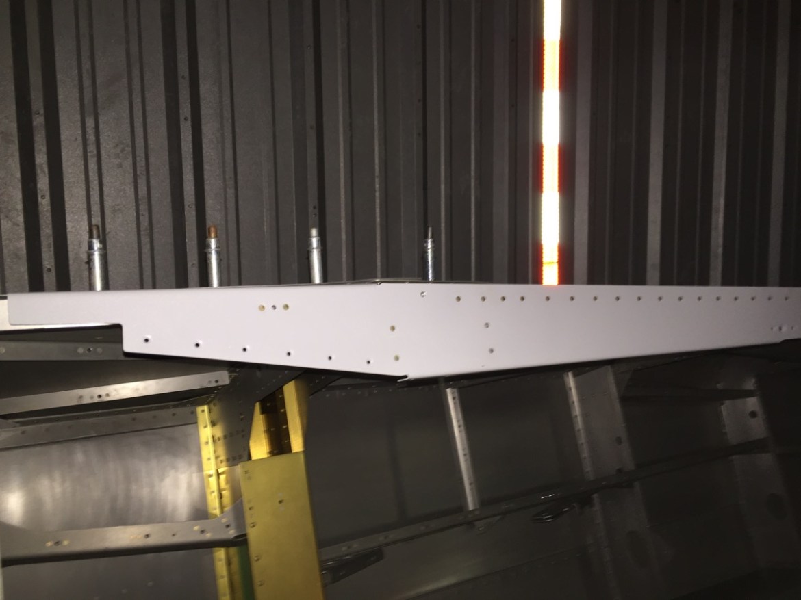
Here you can see the rivets that do not go through the upper fuse skin installed.

I also inventoried and stored all the parts from the finishing kit. There were several mistakes in packing. In almost every instance the bag included rivets a size smaller than indicated. I guess someone had something labeled wrong.   

I have been debating for some time whether or not to modify my side consoles. But you know what? Thinking about it slowing me down. I decided to do them stock for now, and I can change them later on if I so desire. To that end I began working on the right console first. This requires installation of the cover show here so you can drill the locations for the nut plates.

Here I have the console installed in preparation for drilling the bulkhead cap / cover for screws and nut plates.   

The modified bulkheads (due to the new fastback rails) require new holes in the upper portion, and shown here. This also means you need to slightly modify the bulkhead caps to fit.

A little light work with the scotchbrite wheel is all that is needed to make the caps fit.

Next up the left console which houses the throttle quadrant. First step is to remove the tab shown here.   

Then you need to fabricate the cable anchor. This may be a small part, but its a substantial task. First cut to the appropriate dimension. Be sure to read the height required BEFORE adding the radius. There are two measurements immediately next to one another. I read the wrong one, but luckily I was able to salvage it.


I also rearranged some of my parts, and labeled new items. Staying organized is a constant struggle, but certainly helps when you need to find something.   

The cable anchor is match drilled and then you must tap it 8-32 for screws.
  

Here is the pilot hole and centerline I drew. Note the INCORRECT centerline to the right that I drew before fully consulting the drawings.

I was over in Bullock’s hangar, and I noticed that he is finally purchasing age appropriate items. 

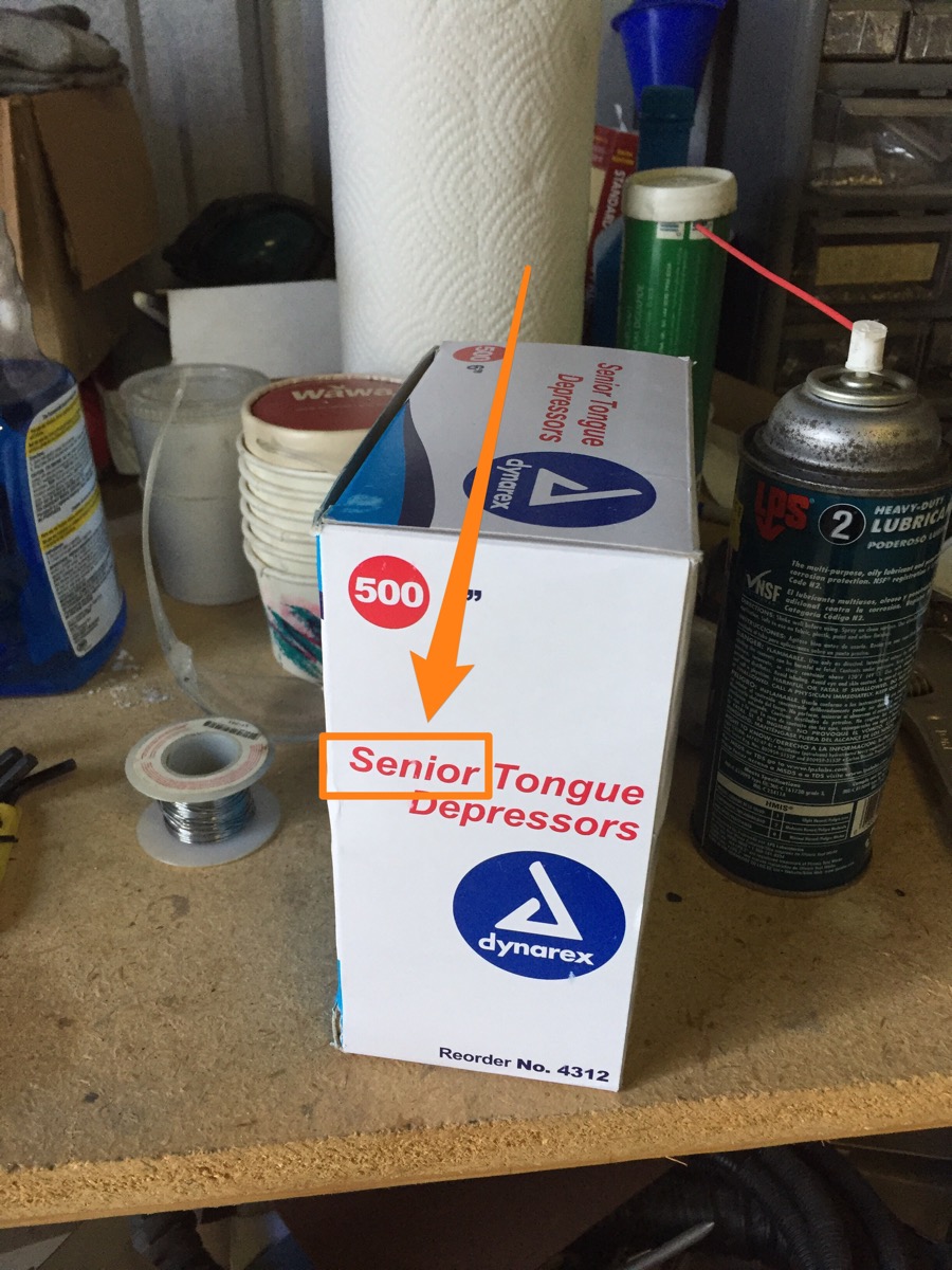
Here you can see my vice being used to provide a stable level surface for the tap. This is a pain in the butt. 3 of the 4 turned out great, but one isn’t. I will likely tap that again for a large size screw.

I am trying to get every part that I can ready for installation in the interior. I haven’t even seen these side panels referenced in the instructions, but preparing them is just a matter of a quick match drilling and deburring.   

My pile of parts ready for priming is growing again. This fuselage may still look almost like the day it arrived, but holy cow is there a serious pile of parts ready for riveting. Sometime soon there are going to be a few posts with major progress! 😀

At this point I’ve almost run out of tasks to do, without either installing the empennage or the wings. Yes, I could begin riveting some items in the cockpit, but its best to keep things open for the time begin. That said, its time to modify the vertical stab for the turtle deck. I took it down off its hanging place to have a good look at what was required.   
  

Here’s a good figure from the Showplanes instructions on the vertical stabilizer modification. Next time!