Fuselage


Fastback 21

I returned to the hangar to find my left fillet fully cured. Step number 1 was sanding a smooth transition. I’m happy with the result.

IMG_0669_2

I used flox to join the right side.

IMG_0670

And I sanded the remaining empennage fiberglass.

IMG_0672 IMG_0671_1

The rear seat back fiberglass top has been waiting completion for some time. Last time, I had sanded and filled what I hoped were the remaining pin holes. I primed it one more time to search for pinholes.

IMG_0673


Fastback 20

In a previous post I cut the instrument panel cover at an angle. Looking at the way the canopy frame is constructed, this is both impossible, and un-necessary. The canopy frame will provide the function I was after, and as a result, the cover MUST be trimmed flush. I made quick work of trimming with my dremel.

IMG_0641

After trimming, I taped the instrument panel. I will file / sand the fiberglass cover to be perfectly flush with the panel.

IMG_0642 IMG_0643

I also began drilling for the nut plates on the forward section of the cover. I will come back and install the nut plates later.

IMG_0647

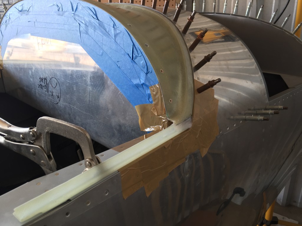
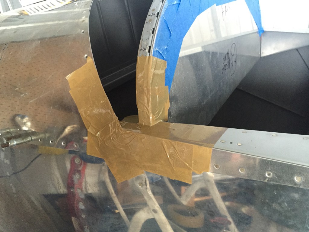
Time to turn my attention to the fillets. I will do these in stages. The first stage is to join the side fillets to the cover. I will then begin work on the canopy frame. When the canopy frame is further along, I will complete the fillets. This will allow me to incrementally adjust both for optimum fit.

IMG_0648

Step number one: tape everything before breaking out the flow and epoxy.

IMG_0649

Here is the filet clamped in place with a flox mixture joining the two fiberglass parts.

IMG_0650

With that curing, I turned my attention to fitting the right fillet. Its a slow process. Measure, trim, check. Sand, check, sand, check… complete.

IMG_0651

I also ran the fiberglass strips for the remaining exposed rivets on the horizontal stabilizer aft of the tip.

IMG_0654


Fastback 19

After fabricating the new instrument panel, I needed to bend the bottom. Unfortunately, the first brake was too small. I have a friend who does HVAC and they have this behemoth brake. It took some experimenting but we were able to get the panel bent.

IMG_0625_1

Here is the panel installed.

IMG_0626 IMG_0627_1

Unfortunately, I had to trim a little bit of the bottom of the frame to get the bend to work. IMG_0628 IMG_0629 IMG_0630

The original Show Planes cover / instructions pre-date the -1 kit, and the frame previously was not pre-drilled. This creates some edge distance issues. I couldn’t use the exact spacing recommended, so after a little thought, I came up with the spacing below for the nut plates. Its not perfect in terms of edge distance, but its for nut plates. Just to be on the safe side, I made a backing strip. No need to introduce any cracks from vibration.

IMG_0631

I used the cover and a light to match drill.

IMG_0632_1

Then I drilled for the nut plate rivets.

IMG_0633

Here is the final product.

IMG_0634

I countersunk the cover. BUT, I started countersinking the wrong side. Whoops! I easily fixed it with some flox.

IMG_0635

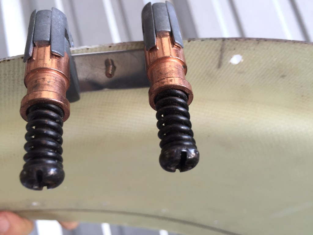
I believe I’ve mentioned this before, but there are two types of countersink bits out there. The one below… sucks. It takes a huge bite out of whatever you are countersinking, and is a pain in the rear.

IMG_0636

I much prefer the countersink bit shown here.

IMG_0637

To countersink the fiberglass, I used a backing strip to keep the countersink bit from wandering.
IMG_0638

(Here is a picture of my flox countersink repair)

IMG_0639_2