Main Fuselage


Fuselage 26 – Mounting the Horizontal Stab

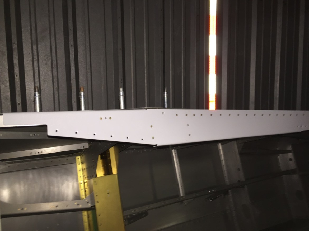
Today is an exciting, and somewhat nerve racking day. Its time to begin attaching the horizontal stabilizer to the fuselage. A few of these bolts require an accurate drill, and leave little room for error. The first step was to sit the horizontal stab in place. The forward spar sits on top of the 1/8 aluminum spacers shown here. 

The rear spar requires a 3/16″ lift. The best spacer to use is a 3/16″ drill bit. Lightly clamp the fuselage in place and center it using the intersection of the rear spar halves.

Here is the centered position marked with the ruler and blue ink. You can see perfect alignment with the intersection of the two spar halves.   

Now its time to clamp the front lightly. The clamps at the rear should be firmly in place to ensure the center position does not move. However, you want some wiggle room in the front as you ensure that horizontal stab is perpendicular to the fuselage.

This is also the time to ensure the horizontal stab is level. Mine appears just ever so slightly higher on the left. However, its true to the fuselage level. I sat a portion of aluminum angle on top of two wooden block spacers.   

Here’s a good picture of the level, angle, and spacers in position.   

After this, you want to verify that the angle of incidence is zero degrees. This is measured between the chord line of the horizontal stabilizer and the top longerons. The tooling holes in the ribs are centered on the chord line. I used a cleco in each tooling hole and then measured. The alignment was correct.
  

To ensure the stab is perpendicular to the fuselage at a 90 degree angle, I measured from the intersection of the cockpit rails to the aft outer corner of each side of the stab.

I offset the starting point at 2 feet to counterbalance the tape measure.   

Now here comes the tricky part. After the fuselage has been leveled and trued in each direction, its time to drill the most difficult holes. These holes will go through the forward spar splice angle, the aft deck, angle and upper longerons. There isn’t much, if any wiggle room. Further compounding the difficulty, is the ambiguity of the diagrams and instructions. The instructions call for the outside bolt to be 1/2″ in from the outside of the upper longeron. I used my small ruler placed between the skin and the longeron to draw the precise location of the outer edge of the longeron. 

I then measured 1/2″ in.   

Here is a good shot of the underneath. You can see the intersection gives little room for proper edge distances. Be sure to start with a small pilot hole so that you can walk the larger drill bits in the direction you need as appropriate.
  

My right outer bolt is too close to the longeron edge for my comfort. Its only just on the good side of edge distances for the angle. This illustrates the futility of trying to have all 3 edge distances in alignment. Some people argue that the longeron is the most important.

The other hole is much more comfortably in edge distance tolerances.   

Here’s why I don’t necessarily buy the longeron being the most important edge distance. The diagram, which is to scale, clearly shows that the hole as positioned by Van’s engineering team does not meet the edge distance requirements. I have marked the appropriate edge distance in blue on the ruler below.    

All this being said, I was rather perturbed by the edge distance of the hole on the right longeron, and I decided to call it a night. I’d need to read up on this issue and give it some thought.


Fuselage 25 – Prep for empennage attachment

My hangar mate’s plane is out for its annual inspection, so I have a few weeks where I have extra room. I decided this was the perfect opportunity to get started on the empennage attachment.

I knew I’d need a second set of hands to remove the fuselage from the rotisserie and get everything situated. Luckily my buddy Mike was willing to help. The first step was to rearrange the hangar as best I could and prepare space for removing the fuselage from the rotisserie.

After we removed the fuselage from the rotisserie, Mike was kind enough to keep my mobile platform in the back of his hangar. While he put that away, I built a quick and dirty fuselage stand from some basic saw horses.

Here you can see the fuselage in its new location. I’ve offset the tail to allow for the empennage to be attached.   

Fancy? Nope. Effective? Yes.

We put the tail feathers in place just to see it. Its a good feeling. This actually looks like a plane! I can’t wait until the wings go on!  

In the next session I will begin work on the actual attachment of the empennage.   


Fuselage 24 – Rails, rudder pedals & more

I’ve done a lot of traveling in November, and I’ve not updated this blog accordingly when I have had time to get to the shop. This post comprises several shop sessions (3 or 4 I think).

First I finished up the cockpit rails. This included rivets that would be under the forward upper fuselage skin.

Here you can see the rivets that do not go through the upper fuse skin installed.

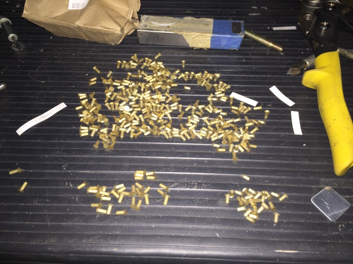
I also inventoried and stored all the parts from the finishing kit. There were several mistakes in packing. In almost every instance the bag included rivets a size smaller than indicated. I guess someone had something labeled wrong.   

I have been debating for some time whether or not to modify my side consoles. But you know what? Thinking about it slowing me down. I decided to do them stock for now, and I can change them later on if I so desire. To that end I began working on the right console first. This requires installation of the cover show here so you can drill the locations for the nut plates.

Here I have the console installed in preparation for drilling the bulkhead cap / cover for screws and nut plates.   

The modified bulkheads (due to the new fastback rails) require new holes in the upper portion, and shown here. This also means you need to slightly modify the bulkhead caps to fit.

A little light work with the scotchbrite wheel is all that is needed to make the caps fit.

Next up the left console which houses the throttle quadrant. First step is to remove the tab shown here.   

Then you need to fabricate the cable anchor. This may be a small part, but its a substantial task. First cut to the appropriate dimension. Be sure to read the height required BEFORE adding the radius. There are two measurements immediately next to one another. I read the wrong one, but luckily I was able to salvage it.


I also rearranged some of my parts, and labeled new items. Staying organized is a constant struggle, but certainly helps when you need to find something.   

The cable anchor is match drilled and then you must tap it 8-32 for screws.
  

Here is the pilot hole and centerline I drew. Note the INCORRECT centerline to the right that I drew before fully consulting the drawings.

I was over in Bullock’s hangar, and I noticed that he is finally purchasing age appropriate items. 

Here you can see my vice being used to provide a stable level surface for the tap. This is a pain in the butt. 3 of the 4 turned out great, but one isn’t. I will likely tap that again for a large size screw.

I am trying to get every part that I can ready for installation in the interior. I haven’t even seen these side panels referenced in the instructions, but preparing them is just a matter of a quick match drilling and deburring.   

My pile of parts ready for priming is growing again. This fuselage may still look almost like the day it arrived, but holy cow is there a serious pile of parts ready for riveting. Sometime soon there are going to be a few posts with major progress! 😀

At this point I’ve almost run out of tasks to do, without either installing the empennage or the wings. Yes, I could begin riveting some items in the cockpit, but its best to keep things open for the time begin. That said, its time to modify the vertical stab for the turtle deck. I took it down off its hanging place to have a good look at what was required.   
  

Here’s a good figure from the Showplanes instructions on the vertical stabilizer modification. Next time!