Fuel Tanks


Fuel Tanks 34 (3.0 hrs)

Today it was time to actually fix the leaks. Before I put proseal inside I wanted to do all the sanding and drilling. This way I could clean up the debris before any wet proseal entered the equation.


Here is the first repair. This is in the first section that houses the flop tube and actually isn’t leaking. I wanted to make sure that the leak which is close to the rib on the other side wasn’t coming from this side. 

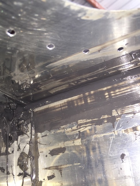
This is the other side of that rib. Yes, its a mess. But its darn hard to work inside a small 4 inch access hole. The best technique I found was to use a syringe to apply a bead and then popsicle sticks to produce a fillet. 

Here is the third and final section for repair. 

Here is how I applied proseal to the wire.   

I also applied a filet of proseal to the outside of the baffle. I know this isn’t the best, but I figured why not. My last task for the day was to flip the tanks baffle down. Proseal, while thick, does follow gravity. Hopefully the proseal will sit over the next week and fully seal those leaks up! I will close the tanks after I make a final inspection. I may need to add more proseal if anything looks out of sorts. I do not intend to do this for a second time!


Fuel Tanks 33 (2.5 hrs)

Today it was time to start repairing the leaking tank. I started with the dreaded task of removing the processed access plate. I’ve read some posts that say this is a gargantuan task. A few have said its easy, but details on it being easy were sparse.

I started by removing the screws. If you look closely you’ll notice a dab of valve grinding compound on the tip of the philips head screw driver. I was skeptical at first too, but this works wonders in stoping your philips screw driver from caming out of the screw. In fact, it works so well that torqued and prosealed screws were a breeze to take out!   

Now I messed around for a bit before I discovered the secret to removing the access plate. I was trying several different tools, heat gun, MEK… no luck. Then I read a post which said use a plastic putty knife (I have something similar) perfectly perpendicular to the access panel and a hammer (I recommend a dead blow). BOOM! The plate was off in no time. If you subtract the time that I fussed about with other methods, this took less than 10 minutes to do. There is no reason to use a cork seal after figuring out how easy this is!

After a little MEK and scotchbrite action, the plate is ready to be put back on. This bay doesn’t technically have a leak, but one leak is close enough to the rib in the next bay that I’m going to seal in here anyways. 

Next I measured where to cut the access plate holes. I was originally thinking to do all four, but decided to do the two I needed and then go from there.   

Like last time i used my leading edge jig and the drill press rotated 180 degrees with a fly cutter to make the holes.     

Well look at this. I did affix at least one cable to the vent line. Maybe thats why I marked this task as complete. We’ll never know…  

Here are the two holes. I went with 4 inch holes. I went a bit bigger last time. but 4 inches is perfect. After looking at the wire, I’m convinced I can proseal all of the wire with only these two access holes.

I inspected each area to see if I could determine where it is leaking. If you look really closely in this photo you can see a gap. Its tiny, but its there. 


Multiple Sessions (12.0 hrs)

This post encompasses several projects over three sessions in the hangar. First up I needed to figure out a way to mount the tail of the fuselage to my rotisserie stand. The axis of rotation is offset from the center of the tail. There are a couple of options for how to mount. I decided to make a padded cradle for the tail. I wrapped a cotton towel around the tail with duct tape. Then I clamped some 2x4s around very tightly to get accurate measurements. A short while later I produced this: 

I didn’t take a good picture of the front mount in my previous session, so here is that. 

And here is the final product for the tail mount. You can see how the center of rotation is offset and how I padded the tail in the cradle. The entire stand is sturdy, but it still makes me nervous. Especially while in the rotated position, its hard to tell how much of a torquing moment may be applied to the engine mount connections or any part of the frame. To protect against any mishaps I will continue to use the adjustable saw horses underneath. Additionally, I have a friend who is giving me an adjustable motorcycle stand. I am going to use that to create a center support that can be adjusted for any position near the center of gravity.


Here is the Hangar 51 mascot showing off his handywork.

That’s not a blue bow. Its poop bags. Keeping it classy.   

Next up, it was time to attach and torque the non-leaking tank to the wing. The screws get between 12 and 15 inch pounds of torque. I used torque seal to mark the bolts that were attached to the z-brackets.     

A trick I learned a little while ago that is seriously awesome; use a small dab of valve grinding compound on the tip of a your philips head screwdriver to avoid “caming” out of the screw head. Works wonderfully.   

I borrowed Mike Bullock’s screw driver click type torque wrench thing-a-majig. Works well.

I double checked that it work with my inch-pound bicycle torque wrench and a philips socket.


Squire enjoyed sunbathing. It was a gorgeous Sunday. 

I also drilled the second line that will hold either the AOA line or the pitot line. I still have two ribs remaining. The two interior ribs to the wing walk doubler are rather difficult to get at. I stopped at Lowe’s on the way home and hopefully I have a solution.    

My final project for the weekend was to complete the wing access panels. First I mounted the skins on the wings and match drilled. Then I deburred and dimpled.  Then I used a technique that I only just learned. Instead of using standard AN426AD3-3.5 rivets which require dimpling both the skin and the nut plate I used NAS1097 Oops rivets with the reduced sized machine heads. These only require a small countersink that you can do with your demurring tool in a few extra passes. Not only is it much quicker, but I think it results in a cleaner and more properly aligned product. There is no reduction in strength either. The nut plates bear the load… the rivets just hold the nut plates in place to prevent rotation.

You can see the results here:

And the final products.