Peter


About Peter

plbarrett.com | Certified Flight Instructor (Single & Multi-Engine, Instrument, and Advanced Ground) | Commercial Helicopter

Fuselage 16 (4.0 hrs)

First up, installing the filter on the compressor. Now, you’re supposed to install filters downline, at least 50′ from the compressor for maximum effectiveness. Right next to the compressor, most moisture will pass straight through. Regardless, I don’t have the room, time, or desire to plumb my portable compressor, so this will have to do. 

A little riveting action holds it all in place!  

With this complete, its time to start the installation of the rudder pedals. To make things easier I removed the bulkheads from the baggage compartment. While I’m at it, I’ll put new primer on those puppies.

I am installing the ground adjustable rudder pedals. The first step is to mark a centerline on the two angles that will hold the rudder pedal axels to the floor.   

Then you need to work on the friction bushings for the rudder pedal axels. I hate working with this plastic. Be careful how you orient the cuts and holes. Van’s, in true form, has provided the absolute bare minimum amount of material.   

After cutting the pieces out, I drilled the largest center hole first. This allowed me to mount the friction bushing and then match drill the final two smaller holes.

I used the first completed bushing as a template for the second.   

Here are the finished products.

Next, I put the rudder pedals together to check certain measurements.   

First you need to check that the outside edge of the angles is 15 1/4″ apart. As you can see, I’m spot on. 

This needs to be 1″ from the floor. Bang on again.  

Now this is where things get interesting. Earlier, I had to drill out, and replace a few AN470 rivets with flush pop rivets. However, the holes for my angles are immediately overtop of these rivets. I double and triple checked the measurements. 

Here’s a close up. You can see the center of the pop rivet almost directly underneath. There is no way this is going to be drilled for another rivet. I suspect it will have to be left empty.
  

The same is true at the other end.

I’ve labeled all the appropriate measurements, per the drawings, so I’m not sure why its so far off.   


As you can see here, the rivet I replace should not be directly underneath the angle. I don’t see any solution except to forego putting a rivet in this location. 

At the forward side, you are supposed to file a slight relief. This will not work in my circumstances. I’d need to file half the angle away! I’m going to sleep on this and then possibly contact Van’s support to see if I’m overlooking something.   

Update August 17, 2015: Solution to the above problem can be found here: http://papalimabravo.com/construction/fuselage/fuselage-18

The last project for the day was to start on the rear rudder pedals. I primed the insides and then drilled for the threaded ends. I cleaned the primer off later with acetone. 


Paint Booth

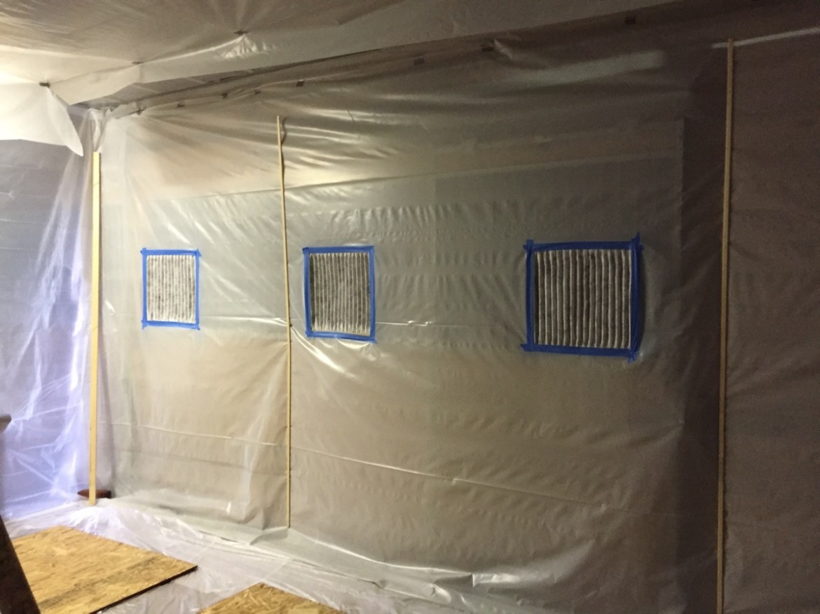
I continued work on the paint booth over the weekend. The first layer of plastic is super thin, and I should have known, not sufficient to withstand the negative pressure (it was cheap!). Regardless it serves a good purpose to create a semi-clean workspace in a barn, that is anything but!  

My first order of business was to install the furnace filter intakes, and the fans facing outward.

Next I began installing the thicker 4mil plastic. I completed both of the walls and most of the ceiling. Then I used 3.5 mil plastic for the two end walls.

The thicker plastic is only 10 feet wide, so I have a small strip on the ceiling at this point that will require some additional plastic.  

I used furring strips to hold the plastic to the wall with 1/2 inch staples.
  

In the next shop session, I finished the ceiling segment and installed another layer of the 0.31 mil plastic underneath the “floor” boards shown here. I then taped the floor seems with duct tape. Show in this photo is the condition of the booth with both fans on. The negative pressure is rather intense, but everything is holding up just fine.

Another photo of the negative pressure effects.   

As you can see the floor billows out a little but the spare wood holds it in place. Bricks hold down the walls, and I still have a few furring tips to install. I also have some 1x1s to install in the corners. After that a little more duct tape sealing and some stapling and the sealing work will be essentially complete.
  

This photo is the entrance. The entire wall is a sliding barn door. Since this will be the entrance point, I can’t use a furring strip. The heavy duty rubber mats I have act as a good seal for the bottom. To close the door on the right and left I will use duct tape and possibly a board that I can screw and unscrew for opening the door.

I still need to hang the four lights, and then complete the sealing work and this puppy will be ready for action.


Finish kit + cowl and extras

A few months ago, Mike Regen stopped by my hangar while fueling up at KDMW. We’d not met before, and its always good to meet a fellow builder. Mike is building an RV-8 in Gaithersburg, Maryland. He invited me down to look at his build, with a big bonus of potentially having several spare items for sale. This weekend I was able to make the trip down.

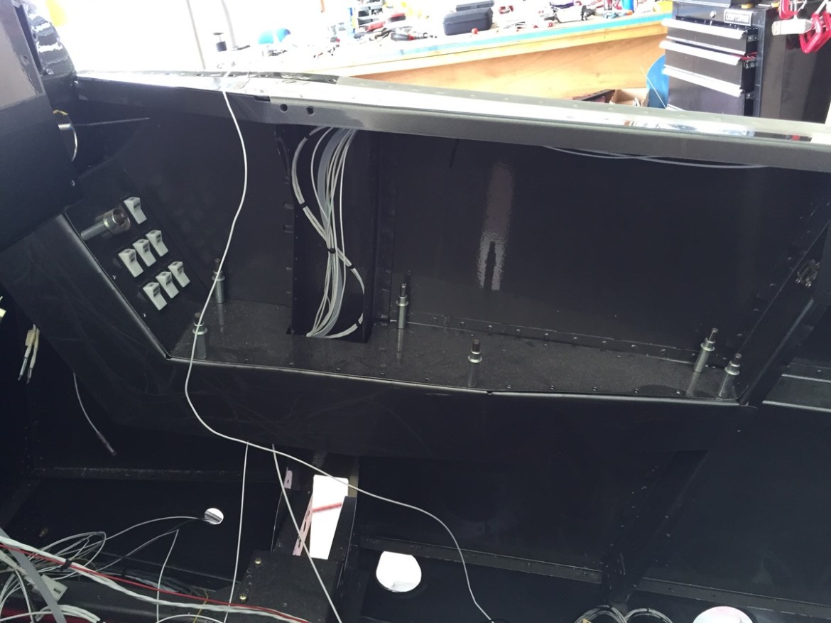
There are a lot of customizations on Mike’s RV-8 that I really like. Here is the first one. He’s built a custom housing for the GRT EIS that mounts in the lower left of the cockpit. He was even nice enough to give me the template for it, should I chose to go that route.  

Here is what it looks like with the EIS in place.

Mike has also installed the larger side consoles with the inclined section for buttons. This is a mod I’m particularly fond of, and I’m giving more than passing consideration to doing this as well.
  

Here you can see the EIS in its final location.

I took several photos of his firewall forward setup, as I plan to install the Sam James plenum, but not the Sam James cowl. The RV-8 requires a prop extension if you use their cowl, and while it is necessarily a show stopper for aerobatics, I see absolutely no reason to extend the arm on which all those forces are acting. Instead, I plan to modify the Van’s cowl for the Sam James inlets and rings.
  

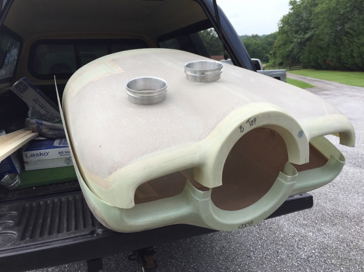
Speaking of the cowl… Mike also had the original Van’s cowl, and he was willing to part with it! I purchased several items from Mike, to include the cowl, axles, Sam James inlet rings, Sam James insert, and a brake reservoir.   

Here you can see the Sam James inlet rings.

This is the eventual modification I will need to make.   

Moving on, I began installing my filters to my compressor in preparation for painting the interior of the fuselage.

I have a large filter / condenser at the tank, and another smaller one at the end of the hose. Additionally, I have some disposable filters, if that is needed.   


I’ve saved the biggest news for last. I ordered my Finishing Kit from Van’s this week! Between the items purchased from Mike, and the items deleted from the Showplanes order, the kit was about $2000 cheaper than normal. I also removed or switched several other items such as the tires and tubes. I am going with the light weight closed bearing tailwheel, and I also added the seat cushion set. I want the seats done sooner rather than later so that I can accurately plan cockpit ergonomics.