Horizontal Stab


Service Bulletin 14-01-31 (6)

Squire made his triumphant return to the hangar today! He had TPLO knee surgery in December as a result of a completely ruptured CCL (ACL). Its been 10 weeks, and he’s healing very well. No lameness and he’s able to start light jogging and other fun activities. He should be able to play fetch in another few weeks. He was super excited to return to the hangar!

Today I set about match drilling the doublers to the spar. The doublers are clamped in place. The position is adjusted by viewing the rivet lines drawn previously, and aligning the bend with the bend in the spar. Its also important to keep an eye on the rivet alignment. The pre-drilled holes in the doubler are offset from the holes in the spar. Additionally, you should ensure you have the proper amount of room between the doublers to allow the mounting of the vertical stabilizer.  For drilling, you begin with the 8 rivet locations in the center of the doubler. You can see those locations here after drilling are attached with clecoes.


After you drill the center, its time to drill the remaining holes that attach the reinforcement angles. An angle drill works nicely. Use the adjacent cleco to aid in alignment.

Here is the finished result. Note the offset rivet immediately above the “L” and the “R”, this denotes the top of the doubler. Additionally, you will note the offset rivet on the lower side second from the inside. This is normal and is a match drill location. I’m very happy with how this has turned out, and I will sleep comfortably knowing the spar is strengthened!


Next I fabricated the angles that will be used to attach the HS-405 ribs after they have been trimmed.

And finally, I primed all the parts before re-installing. In the next session, I should be able to rivet everything together and call this service bulletin complete!

Session time: 4 hours.


Service Bulletin 14-01-31 (5)

Tonight was my first time working on the project in over a month. I finished my MBA program in December and began a Master’s in Engineering in late January. My undergrad is in electrical engineering, but I guess I had chosen to forget that engineering is far more difficult and requires a greater commitment to studying. You can’t BS or fall behind in an engineering degree! As a result, the plane has been put on the back burner while I’ve worked to brush up on topics that are considered pre-requisite knowledge, but aren’t not areas I’m well versed in, such as programming with C.

Anyways, back to the plane. The first two photos are photos I completed in the last session. I don’t believe I had taken good photos previously. The relief notches are complete as is the removal of the spar corners. Tonight I cleaned up all the edges with sand paper and scotch-brite.


I also cleaned up a few rough spots on the reinforcement angles.

I removed the forward flange of the HS-405 ribs. These will be replaced with an piece of angle. With the addition of the spar doublers, the HS-405 will no longer fit, necessitating this change.

Here is the result. It is also necessary to radius the outer edge to rest against the attaching angle. 

Next I deburred the spar reinforcement angles. Then I drew the rivet lines. These lines run through the centerline of the pre-punched rivet holes. The offset rivet marks the top side of the HS-00001 doubler. The line will be used to align with the holes in the spar (shown below).

Here are both side by side. The top side of each doubler will rest against the intersection of the web and flange on the front spar, and it is necessary to radius the edge here as well. 

Here you can see how the line I drew is used to align the doubler.

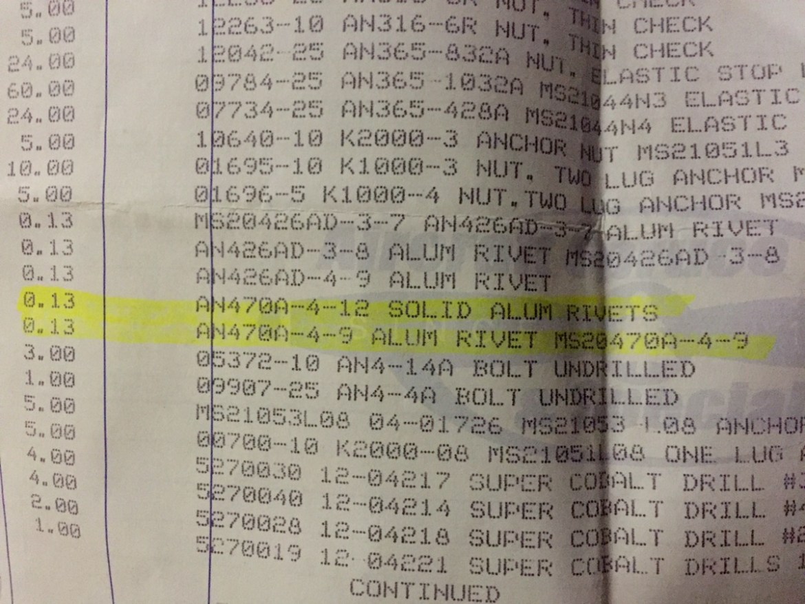
And finally, on a completely separate note, I recently made a hardware order from Aircraft Spruce. While doing so, I did not immediately notice that they have both the AN-XXXA rivets on the same page as the AN-XXXAD rivets. The -A rivets are SOFT and are NOT for use in structural components. I accidentally ordered two sets, shown here. Why ACS would put them on the same page is beyond me. I’m willing to bet I’m not the only person who has made this mistake. Luckily it was only 2 types. I already mixed them with the ones I have, so I’ll need to replace them all.

Hopefully, I’ll be able to find some time in the coming weeks for the project, but the next 3 months are going to be slow. I will not take as many classes next term as I am this term, thats for sure!


Service Bulletin 14-01-31 (4)

Lots of time in the hangar, without a ton to show for it. Today was challenging.

First I set about cleaning up a small nick I had placed in the spar. The drill had slipped during drilling of the rivets, and I wanted to clean up that surface. Unfortunately it was in a difficult position on the corner of the web and flange. I had to remove additional skin rivets and then slowly sand the area down. This was very slow going with limited space to maneuver. You can see the end polished result below.  

I also made the relief notches. Here you can see the start. The red lines mark the width and depth of the notch. 

You can see a completed notch at the bottom of this photo next to the first spar corner I removed. The process here is to wedge the stainless steel between the spar and the skin and then use a dremel to make the cut. Still space is difficult and getting a perfectly clean line is difficult.

I used a two by four to wedge the skin open to help file the rough edges and round the corners. Very slow going as my hands and arms don’t contort the right way and space was very limited.

Here’s a good picture of a completed relief notch and spar modification. Of note, the RV-7 plans explicitly call out the relief notch, whereas there is not mention of the relief notching the RV-8 plans (diagrams or instructions).